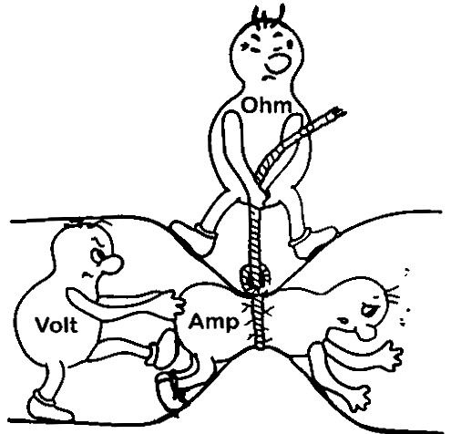
Ohm’s Law Visualized

The above picture is one of the best depictions I’ve seen defining the fundamental equation relating voltage, current, and resistance, which we call Ohm’s Law.
Ohm’s Law is defined as \(V = IR\).
Although this form of the equation is simply stated as voltage is equal to current times resistance, the equation’s meaning is much deeper. Let’s take a closer look.
Resistance (Resistors)
In a closed circuit, resistors, measured in Ohms, are primarily used to limit the flow of current in the circuit. This is easily visualized in the picture above as we see the resistor squeezing the pipe that allows the current to flow through it. Given a fixed voltage, the larger the resistance, the less current that will flow through the circuit.
Current (Electrical)
Electrical current is measured in Amperes (Amps) and is essentially defined as the flow rate of electrical charges in a circuit with respect to time. Electrical charges are measured in Coulombs, and Amperes are measured in Coulombs per second. Rewriting Ohm’s Law to solve for current, we can see that the current in a circuit is equal to voltage divided by resistance. Current is directly proportional to voltage and indirectly proportional to resistance. Hence, given a fixed voltage, the current in a circuit will decrease as resistance increases, and current will increase if resistance decreases. For a fixed resistance, current will increase with an increase in voltage, and decrease with a decrease in voltage. The picture above clearly depicts this as well. The greater the resistance, the less current will flow given a fixed voltage.
Voltage
Voltage, measured in Volts, can be difficult to conceptualize. Voltage can be thought of as the amount of energy required to “push” current through a circuit. Ohm’s Law states that voltage is directly proportional to current and resistance. To maintain a fixed current through a circuit, an increase in the circuit’s resistance requires an increase in voltage. Likewise, a decrease in resistance requires a decrease in voltage to maintain the same current in a circuit. Hence, more resistance means more “push,” and less resistance means less push. The picture above provides justification for this concept.
Fluid-Flow Analogy

Fluid flowing through a pipe is the mechanical analogy to electrical current flowing through a circuit made of electrical conductors (usually copper wires). The amount of fluid flowing through a pipe is synonymous with the amount of current flowing through a circuit’s wires. The size of the pipe is synonymous with the size of the resistor. A decrease in pipe size will limit the flow of fluid through a pipe the same way that an increase in resistance will limit the flow of electrical current through a circuit. An increase in pressure between a pipe is required to maintain the current flowing through the pipe as pipe size decreases. This is synonymous with the increase in voltage requirement to maintain electrical current flow within a circuit given an increase in electrical resistance.
